This article was first posted on January 9, 2013; it was revised on January 27, 2013.
In this post we will think about diffraction of a beam of x-rays, with a single wavelength, λ, as in post 22.14. But here we will consider the special case where the scattering object is an ideal crystal. My purpose is not to describe experimental techniques but to think about the principles involved. In post 22.21, we saw that an ideal crystal is an arrangement of atoms (that may be bonded together in molecules) or ions in a regularly repeating three-dimensional pattern. We also saw, in post 22.21, that we can consider an ideal crystal as the convolution of a lattice with the repeating arrangement of atoms or ions – called the unit cell. Therefore, the Fourier transform of the crystal is the Fourier transform of the electron density in a unit cell multiplied by the Fourier transform of the lattice (see post 22.20). In post 22.24, we saw that the Fourier transform of a lattice was non-zero only at the reciprocal lattice points indexed by three integers, h, k and l – the Miller indices. So, the Fourier transform of a crystal is non-zero only at the reciprocal lattice points. An observed diffraction pattern is formed by the region of K-space that intersects the Ewald sphere, as described in post 22.23. This means that we can only observe reciprocal lattice points that lie on the surface of the Ewald sphere.
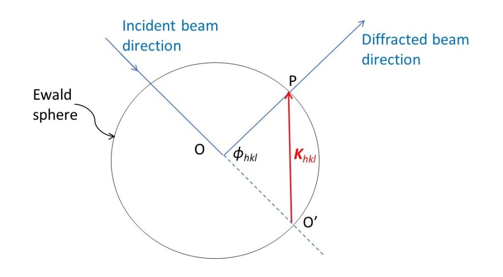
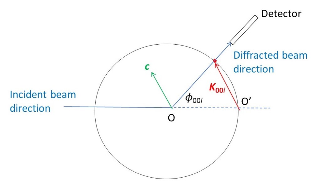
The picture above is a section through the Ewald sphere with a reciprocal lattice point (Miller indices h, k, l) on its surface at P. In this picture, O is the origin of real space and O’ is the origin of K-space. The vector Khkl, that defines the position of P is the line O’P. The angle O’ÔP is the scattering angle, ϕhkl. From post 22.23 we know that
Khkl = (4π/λ)sin(ϕhkl/2).
And from post 22.24 we know that
Khkl = ha* + kb* + lc*
where a*, b* and c* are the reciprocal lattice vectors. Remember that, in vector notation, a symbol in bold represents a vector (both its modulus and its direction) but the same symbol not in bold represents only the modulus. It then follows that the position of the point, in K-space, where we observe the (h,k,l) reciprocal lattice point has a scattering angle given by
sin(ϕhkl/2) = (λ/4π)(ha* + kb* + lc*).
We define the function arcsin (analogous to arccos and arctan) by
if sinθ = x then θ = arcsinx. Then
ϕhkl = 2arcsin(λ/4π)(ha* + kb* + lc*). (1)
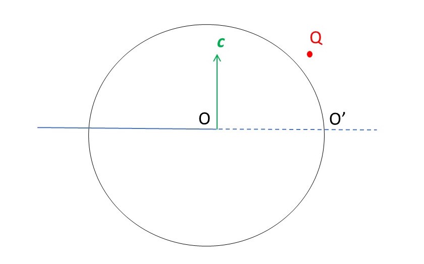
How can we make a reciprocal lattice point lie on the surface of the Ewald sphere? The picture above shows a crystal at O, the origin of real space, with its unit cell vector, c, in the vertical direction. The reciprocal lattice point at Q does not lie on the Ewald sphere. But, if we rotate the crystal (not necessarily through 360o) about c, Q will pass through the surface of the sphere. Why? Because, when we rotate the crystal, we rotate the unit cell vectors a, b and c. According to the Laue equations, we then rotate a*, b* and c* by the same angle, about a parallel axis in K-space. Then we can detect the x-rays passing through Q’, the rotated position of Q.
How can we arrange to make c vertical? If the crystal has a defined shape, we simply choose an axis of this shape (like the length of a needle-shaped crystal) – this is likely to be in the direction of one of the unit-cell vectors that we can define as c.
Many crystals have a unit cell with α (the angle between b and c) and β (the angle between a and c) are both equal to 90o.If γ (the angle between a and b) is not equal to 90o, they are called monoclinic crystals. But if γ = 120o, when they are called hexagonal crystals. There are crystal systems that resemble the monoclinic system but have γ = 90o; these are the cubic, tetragonal, orthorhombic and rhombohedral crystal systems. The remaining crystal system is the triclinic for which α, β and γ are not equal. Since I have defined angle that is not equal to 90o, in the monoclinic system to be γ, we say that I have chosen c to be its unique axis; many books choose b to be the unique axis, then β is not equal to 90o.
The rest of this post is correct for all crystal systems except triclinic, to make the explanations easier to understand. The general principles apply to all crystal systems. But some of the conclusions and equations may not apply.
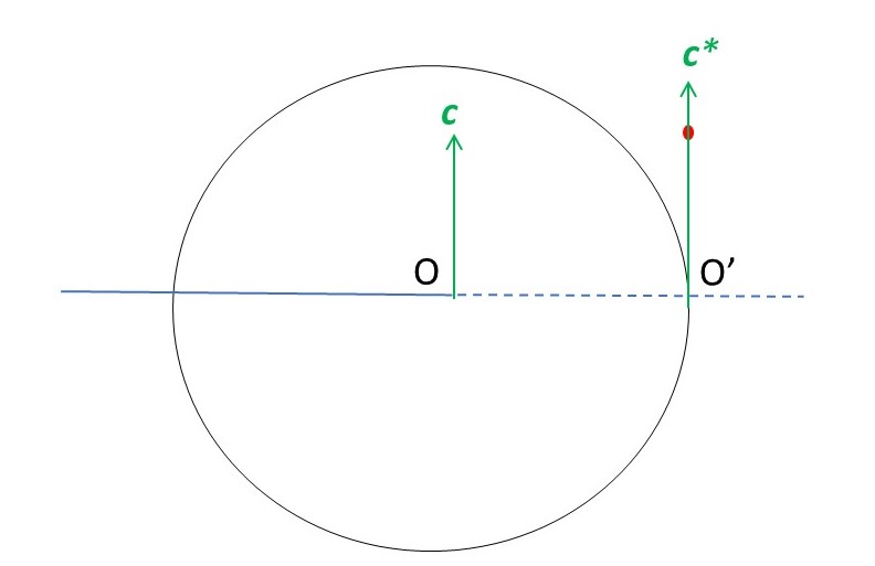
Now let’s think about recording reciprocal lattice points on the c* axis. According to the Laue equations, c* is perpendicular to a and b. And, for a monoclinic crystal, c is perpendicular to a and b. So c and c* are now in the same direction. In the picture above, we see that a reciprocal lattice point on the c* axis (that is when h = k = 0) cannot intersect the Ewald sphere, when c is vertical – even if we rotate the crystal about c. To observe this point, we must rotate the crystal about an axis perpendicular to the plane of the picture, as shown below.
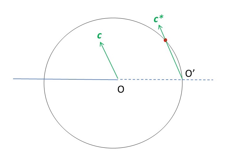
How do we know when this reciprocal lattice point lies on the surface of the Ewald sphere? We must rotate the crystal in increments and, for each angular position of the crystal, we rotate a detector about an axis through O, perpendicular to the plane of the picture. A reciprocal lattice point lies on the surface of the Ewald sphere when x-rays are detected, as shown in the picture below.
From equation 1,
ϕ00l = 2arcsin(lc*λ/4π) (2)
so that, when l = 0, the scattering angle is zero and, when l = 1, it is given by
ϕ001 = 2arcsin(c*λ/4π).
The picture below shows how, by rotating our detector, we can detect the values of ϕ00l for different values of l. If our results don’t look like this, we must adjust our axis of rotation.
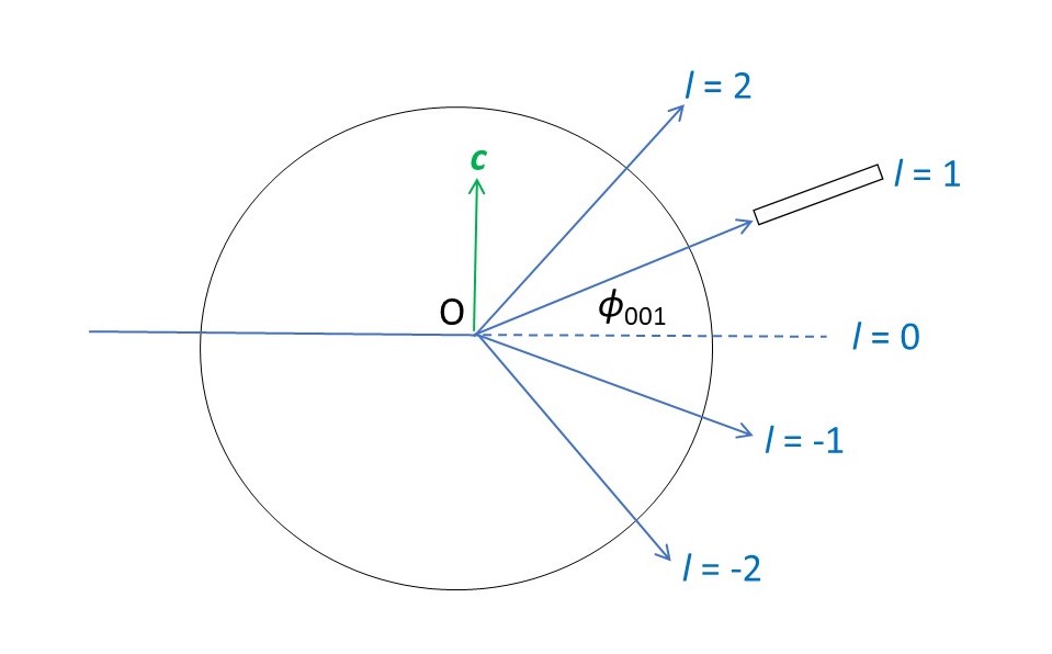
If we know the value of λ, can calculate c* from the observed values of ϕ00l by modifying equation 2, to give
c* = (4π/lλ)sin(ϕ00l/2).
Now let’s suppose we rotate our detector to the l = 0 position, in the picture above, and then rotate it about the c-axis. We can’t really do this because the incident beam would be so intense, even after passing through the crystal, that it would damage the detector. So we need to place a metal stop to absorb x-rays travelling in this direction. But we can still rotate the detector about its new axis, on either side of the stop.
Both a* and b* lie in the plane of the rotating detector since both are perpendicular to c, according to the Laue equations. According to equation 1, the detected scattering angles are given by
ϕhk0 = 2arcsin(λ/4π)(ha* + kb*).
These angles can be used to assign values to h and k and so determine a* and b*, to explain the positions of the reciprocal lattice points, as described in appendix 1. So, by rotating the crystal about its c-axis, we can determine values for a* and b*. By definition, a* = 1 on the a* axis and b* = 1 on the b* axis. So, when we have assigned values of h and k to the reciprocal lattice points, we know the value of γ* (the angle between a* and b*). Since a* is perpendicular to a and b* is perpendicular to b, we can write
γ* + γ +180o = 360o or γ = 180o – γ*.
From the expression for the cosine of the sum of angles and the properties of the sine and cosine of 180o post 16.50
cosγ = cos180ocosγ* – sin180osinγ* = cosγ – 0 = cosγ*
Now we can find the values of a, b and c.
According to the Laue equations c* is perpendicular to a* and b*. And, in our monoclinic example, c is also perpendicular to a* and b*. So the angle between c and c* is zero. The Laue equations state that
c.c* = 2π.
From the definition of the dot product
c.c* = cc*cos0= cc* so c = 2π/c*.
Similarly
a.a* = aa*cosγ* = aa*cosγ and a.a* = 2π so a = 2π/a*cosγ
and
b.b* = bb*cosγ* = bb*cosγ and b.b* = 2π so b= 2π/b*cosγ
We have now determined the values of a, b, c and γ and so have defined the dimensions of the monoclinic unit cell.
Related posts
22.24 Reciprocal lattice
22.23 K-space
22.22 Fourier transform of a one-dimensional lattice
22.21 An ideal crystal
22.14 X-ray diffraction
Follow-up posts
23.3 X-ray diffraction by a crystal
23.4 X-ray crystallography
Appendix
We might expect the first scattering angle we observe, when rotating the crystal about c, to have h = 1 (defining a* to be less than b*) and k = 0. The next is likely to have h = 0 and k= 1. This gives us provisional values for a* and b*. We can use these values to predict scattering angles for other h, k and l values. If the predictions don’t match the observations, we need to try again. Perhaps a* = b*, then angles for (1,0,0) and (0,1,0) will be the same. Once again, we can predict other scattering angles and see if they agree with observation. When predictions and observation match, we have found the true values of a* and b*.
The procedure for finding h, k and l values is called indexing the diffraction pattern.
