While I was compiling the index to this blog, I noticed that I had written several posts about mechanical simple harmonic oscillators but hadn’t written anything about electrical simple harmonic oscillators– the subject of this post.
A simple harmonic oscillator is a system that oscillates indefinitely by exchanging potential and kinetic energy. In a real system there will be some dissipation of energy and so cannot oscillate for ever – the simple harmonic oscillator is a model for a real system and not an exact description of it. Examples are a pendulum and a vertical oscillating spring. Both systems will dissipate some energy because, for example, of the viscosity of the air. But the simple harmonic oscillator describes the behaviour of both reasonably well. For example, a mass bouncing on the end of a spring, oscillates with a frequency of
f = (1/2π)(k/m)1/2 (1)
where k represents to stiffness of the spring and m is the mass of the object hanging from its end.
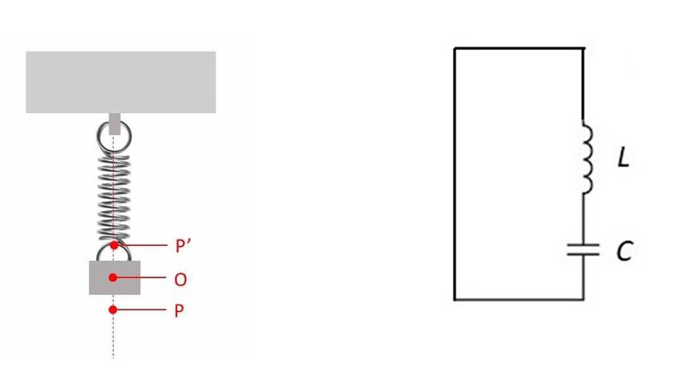
In the picture above, the vertical spring supports a mass; the force, exerted by the gravitational field of the earth, on this mass stretches the lower end of the spring from P’ to O. Now an additional force is applied to stretch it to P. This additional stretching of the spring gives it potential energy. When this additional force is removed, the potential energy is converted into kinetic energy. This kinetic energy tends to return the spring to its equilibrium position. But it does not stop at O because all its potential energy is converted into kinetic energy – so it continues to move upwards, converting kinetic energy into gravitational potential energy as it continues. When all the kinetic energy has been converted into potential energy, the direction of movement changes as the mass begins to fall. If the system did not dissipate energy, it would oscillate indefinitely. Whenever the kinetic energy is zero, the energy of the system will be stored as potential energy that will be used to restore motione. For example, the spring, in the picture below, oscillates between P and P’; at O the kinetic energy is maximum but the system has no potential energy, as described in post 18.11.
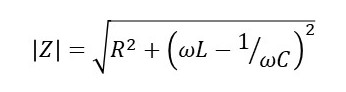
From the analogy between electrical and mechanical systems, we can see that a capacitor behaves like the spring (because it stores energy) and an inductor behaves like the mass (because it is the inertial component of the system opposing change). Then an electrical simple harmonic oscillator will consist of the circuit shown above, in which a capacitor discharges through an inductor.
Initially, the charged capacitor has potential energy. As it discharges, charges begin to move around the circuit – the moving charges have kinetic energy. But the inductor opposes the movement of charge in the circuit. In the mechanical system, a stretched spring has potential energy. When the spring is released, this potential energy is converted into kinetic energy. But the mass hanging on the end of the spring opposes the change in motion, so that the system oscillates. The charge in the electrical circuit oscillates in exactly the same way. Returning to our analogy between electrical and mechanical systems (and applying it to equation 1), the charge (and, therefore, the current) oscillates with a frequency of
f = (1/2π)(1/LC)1/2 (2)
where L is the inductance (analogous to inertia) of the inductor and C is the capacitance (analogous to inverse stiffness or compliance) of the capacitor. A real electrical system will have some resistance, dissipating energy, so the simple harmonic oscillator is a model for a capacitor discharging through an inductor in a circuit with negligible resistance.
We can also analyse the behaviour of the electrical circuit directly, without needing to think about the analogy with a mechanical system. In the appendices, I have done this in three different ways.
This blog now has an INDEX.
Related posts
19.17 Computer modelling – the simple harmonic oscillator
18.24 Analogies between electrical and mechanical systems
18.23 Frequency response and resonance in electrical systems
18.22 Inductors and impedance
18.21 Inductors and inductance
18.20 Capacitors and impedance
18.19 Capacitors and capacitance
18.17 Euler’s relation, oscillations and waves
18.8 Natural frequency and resonance
18.11 Motion in a circle, the simple harmonic oscillator and waves
18.7 The simple pendulum
18.6 The simple pendulum: a simple harmonic oscillator
Follow-up posts
22.18 Coupled oscillators
24.6 Damped simple harmonic ocillator
24.7 Driven oscillator
26.2 More about the simple harmonic oscillator
Appendix 1: Analysing the electrical simple harmonic oscillator using the concept of impedance
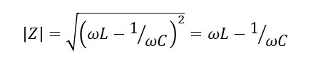
The modulus of the complex number that represents the impedance of an electrical circuit containing a resistor, an inductor and a capacitor is given by
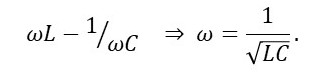
where R is the resistance of the circuit and ω is the angular frequency of the oscillating current. When we can consider that R = 0, the impedance becomes
In our electrical simple harmonic oscillator, charge flows from the discharging capacitor; there is no other potential difference causing charge to flow. So, the current is maximised when │Z│ = 0, that is when
The relationship between angular frequency and frequency is that ω= 2πf, so that this result is equivalent to equation 2.
Appendix 2: Analysing the electrical simple harmonic oscillator using the concept of electrical potential
The capacitance of a capacitor is defined by
C = Q/V’
where Q is the stored charge and V’ is the potential difference across the capacitor. When the capacitor discharges, it creates an equal and opposite potential difference in the circuit it discharges into. This potential difference is
V = –V’ = – Q/C.
The inductance, L, of an inductor is defined by the equation
V = L(d2Q/dt2)
when V is the potential difference causing charges to move through the inductor. The term (d2Q/dt2) represents double differentiation with respect to time. If this potential difference is created by a discharging capacitor
Ld2Q/dt2 = – Q/C. or d2Q/dt2 = – Q/(LC). (B1)
To solve this differential equation, we will consider a trial solution of the form
Q = Q0eiωt (B2)
where Q0 is the value of Q when t = 0, e has a value of approximately 2.718, i is the square root of -1 and ω is an angular frequency. Differentiating this trial solution with respect to t gives
dQ/dt = iωQ0eiωt
d2Q/dt2 = –ω2Q0eiωt = –ω2Q (B3)
Comparing equations B1 and B3, the trial solution works when
ω= 1/(LC)1/2.
Noting the relationship between frequency and angular frequency (appendix 1), this result is equivalent to equation2.
Differentiating equation B2 gives the current in the circuit
I = dQ/dt = iωQ0eiωt = iωQ0cos(ωt) – ωQ0sin(ωt).
The final step comes from Euler’s relation. The result is a complex number. Since the current in the circuit must be real, it is represented by the real part
I = – ωQ0sin(ωt) = – I0sin(ωt)
where I0 is the peak value of the current; the minus sign simply represents the (arbitrary) direction in which the oscillating current is flowing.
Appendix 3: Analysing the electrical simple harmonic oscillator using the concept of energy
From the analogy between electrical and mechanical systems, the charged capacitor has an energy of Q2/2C and the energy of the current flowing in an inductor is LI2/2 = (L/2) (dQ/dt)2; the final step comes from the definition of current, where t represents time.
Since all the charge in the circuit came originally from the charged capacitor,
(L/2)(dQ/dt)2– Q2/2C = 0 or L(dQ/dt)2 = Q2/C.
Differentiating this result with respect to t gives
2L(dQ/dt)(d2Q/dt2) = (2Q/C)(dQ/dt)
as described in post 18.6. Dividing both sides of this equation by 2(dQ/dt) gives
d2Q/dt2 = – Q/(LC).
This result is identical to equation B1 and so has the same solution.
