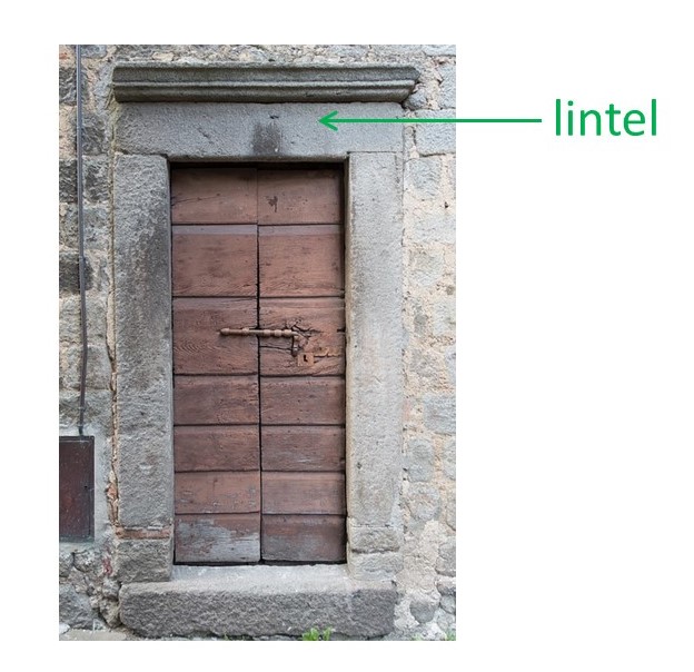
A door, or a window, fills a hole in a wall. The wall above the hole is supported by a horizontal beam, called a lintel. Gravity exerts a force Mg on the mass, M, of the wall above the beam, where g is the acceleration due to gravity, as explained in post 16.16. Note that the beam also has to withstand the gravitational force exerted on itself; so M is strictly the mass of the mass of supported wall plus the mass of the beam. (In the rest of this post, we will assume that the mass of the beam is negligible.) But, according to Newton’s third law of motion, the beam pushed back, with an equal and opposite force, to support the wall above it. If the mass of the wall is too high, the stress induced in the beam will fracture the beam. So, beams are designed to support their intended load without fracture.
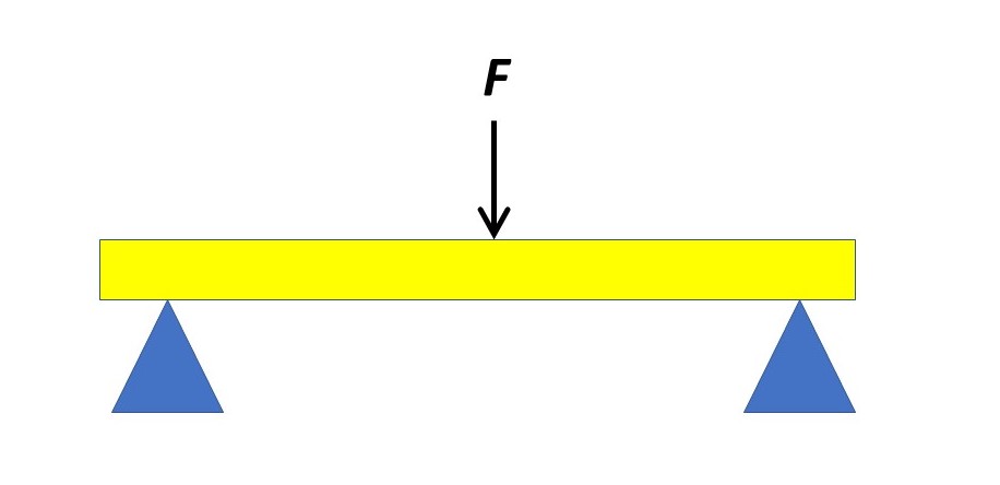
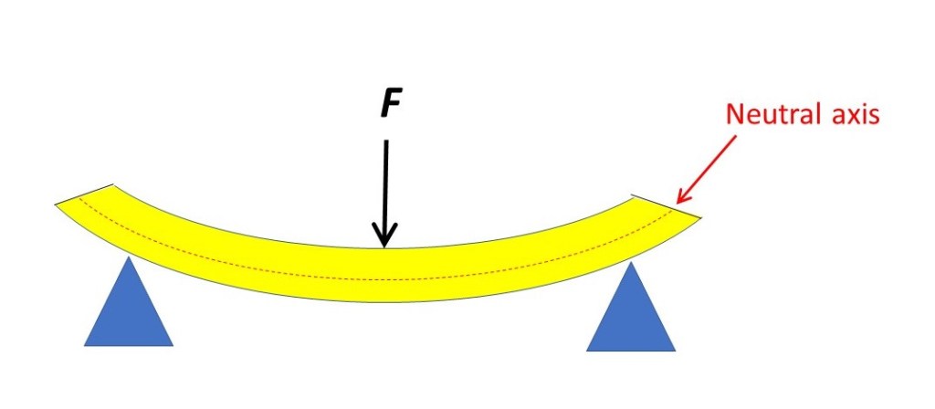
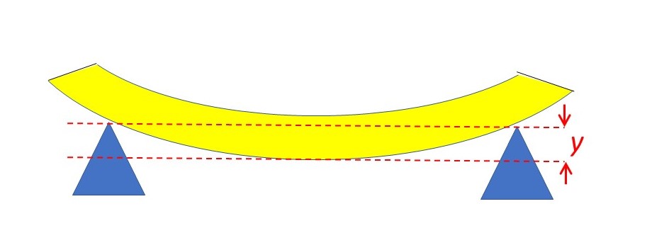
How does a beam work? In the picture above, a force, F, acts vertically downwards on the centre of a horizontal beam that is supported at both ends. As a result, the beam is deformed into a curve, as shown below. The top surface of this curved beam is shorter than before – so it is in compression. The bottom surface is longer – so it is in tension. If the beam is homogeneous and has a constant cross-section, the plane between the top and the bottom will not be deformed. This plane is called the neutral axis. The name “neutral axis” is confusing because an “axis” is a line; but the “neutral axis” is really a plane that appears as a line in a two-dimensional picture, like the red dashed line in the picture below.
If the beam is made of an elastic material, it will tend to return to its original shape and dimensions when the deforming force is removed. The force that would return it to its original state is the force that is exploited in a beam to oppose the applied force.
In the picture below, the deflection, y, of the beam is its maximum displacement resulting from the applied force F.
For a uniform beam with a rectangular cross-section of height h and width b, y is given by
y = (FL3)/(4Ebh3) (1)
where E is the Young’s modulus of the material of the beam. The maximum tensile stress induced in the beam is at its lower surface, because that is where the tensile strain is a maximum, and is given by
σmax = (3FL/2bh2) (2).
Similarly, the maximum compressive stress is at the top of the beam because that is where the compressive strain is greatest. If σmax exceeds the yield stress of the material of the beam, the beam will be permanently deformed (the material of the beam will have undergone plastic deformation). If σmax exceeds the ultimate tensile stress of the material of the beam, the beam will fracture. The designer of a structure must choose a beam that does not permanently deform or fracture.
Note that there is also shear stress in the deformed beam because it has changed shape.
We can generalise equations 1 and 2 for any uniform cross-sectional beam shape to give
y = (FL3)/(48EI) and σmax = (FLh/8I) (3)
where I is the second moment of the cross-section area of the beam; rotational inertia is the second moment of mass but I is the second moment of area, as described in the appendix.
So far, we have considered a horizontal beam loaded at its centre. If the beam is loaded uniformly between its supports, with a total force of modulus F, then equation 3 becomes
y = (5FL3)/(384EI) and σmax = (FLh/16I) (4).
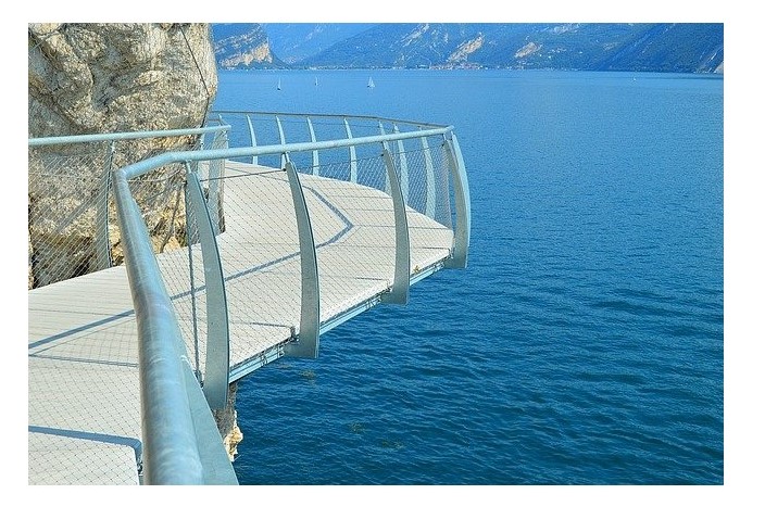
A beam need not be supported at both ends. The walkway, in the picture above, is supported by a beam that is joined to the cliff at one end but is unsupported at the other end. A beam like this is called a cantilever. The picture below shows a cantilever that is loaded at its end.
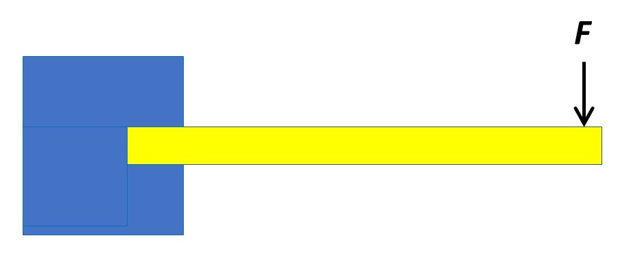
Then equation 3 becomes
y = (FL3)/(3EI) and σmax = (FLh/2I) (5),
where the maximum stress is at the supported end of the beam. For a cantilever uniformly loaded along its length equation 5 becomes
y = (FL3)/(8EI) and σmax = (FLh/4I) (6).
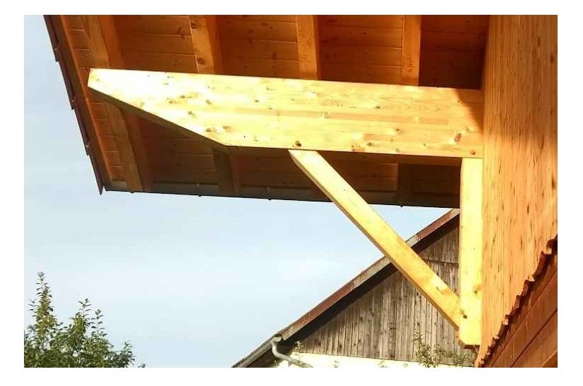
In practice, a cantilever may have additional support, as shown in the picture below.
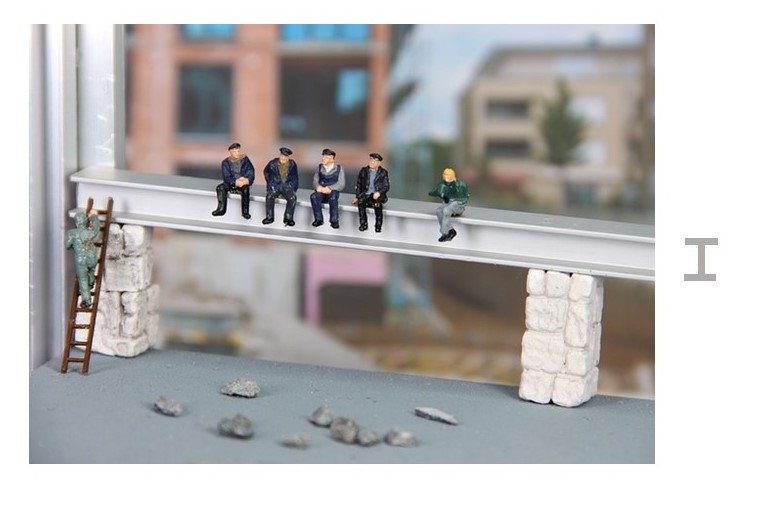
Beams need not have a rectangular cross-section. A common shape is shown in the picture above; the cross-section of the beam is shown on the right-hand side of the picture; it has more material at the bottom (where the tensile stress is greatest) and at the top (where the compressive stress is greatest) but less in the middle (where these stresses are low). Beams with this shape are made by rolling steel and the result is called a rolled steel joist, or RSJ (“joist” is another word for a beam).
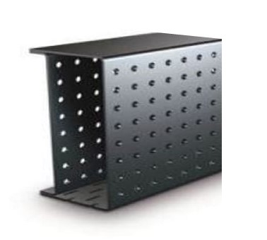
Modern beams, like the one shown above, are often designed to reduce the material (and, hence, the mass) of the beam even more while retaining stiffness and strength. The reduced mass makes the beam much easier to position, especially when introducing a lintel into an existing structure.
In this post, I have given many results without derivation. I intend to show how these results are derived in a later post.
Related posts
20.2 Deformation of objects
20.19 Deformation of objects – changes in shape
Follow-up posts
21.18 Statically indeterminate systems
21.19 Bending a beam
21.20 More about beams
Appendix
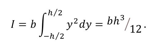
The purpose of this appendix is to show how second moment of area is calculated and that I = bh3/12 for a beam with a rectangular cross-section of height h and width b, as shown in the picture below. The mathematics used here is explained in posts 17.19 and 17.23.
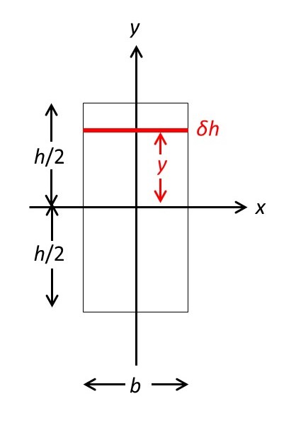
The centre of the cross-section of the beam defines the origin of a Cartesian coordinate system in which the x-axis is horizontal and the y-axis is vertical, as shown. In three dimensions the z-axis would lie along the axis of the unbent beam and point upwards out of the plane of the picture. So, we can think of a horizontal beam as bending around the x-axis.
The picture shows an element strip of the cross-section, coloured in red, of infinitesimal height δh. This strip has an infinitesimal area
δA = bδh
and its second moment of area is defined to be
δI = y2δA = by2δh.
The second moment of the entire cross-sectional area is given approximately by the sum of the second moments of all the strips that make up the cross-section of the beam. In the limit that δh tends to zero, this approximation becomes exact and the second moment of area is then given by the definite integral