In post 20.2 we saw that forces can change the dimensions of an object; they can also change its shape.
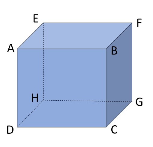
Change in shape without changes in dimensions is called shear. The picture above shows a cube ABCDEFGH. Let’s think about what happens when we apply a force f (posts 17.2) perpendicular to the line BF and fix DH. The picture below shows the effect of this force on the face ABCD of the cube if it leads to changes in shape while the distances AB, BC, CD and DA remain unchanged; A moves to A’, B moves to B’, C moves to C’ and D does not move. This is an example of pure shear.

The shear strain is defined to be the angle γ that is the angle between AD and A’D plus the angle between DC and DC’. The angle γ is a measure of the change of shape, independent of the dimensions of the object. Tensile and compressive strains were defined as a length divided by a length and so are dimensionless (post 20.2). So, does shear strain have different units (post 17.41) to tensile and compressive strain? No – because an angle, measured in radians, is defined by a length divided by another length (post 17.11).
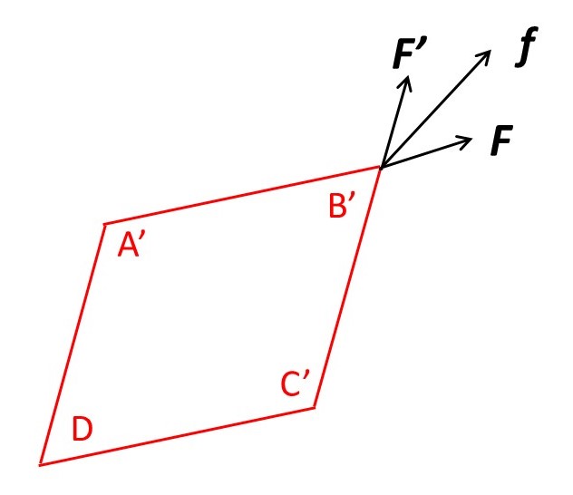
The picture above shows that f can be considered as the resultant (post 17.2) of a force F, acting in the direction of A’B’ and a force F’ acting in the direction of C’B’. F and F’ have the same magnitude and make equal angles with f. If A is the area of one of these faces, then the magnitude of the shear stress is defined to be
σs = F/A.
Note that A does not change during deformation of the cube. Also, be careful not to confuse A, written in italics, that represents the area of a face, and A that marks a corner of the cube.
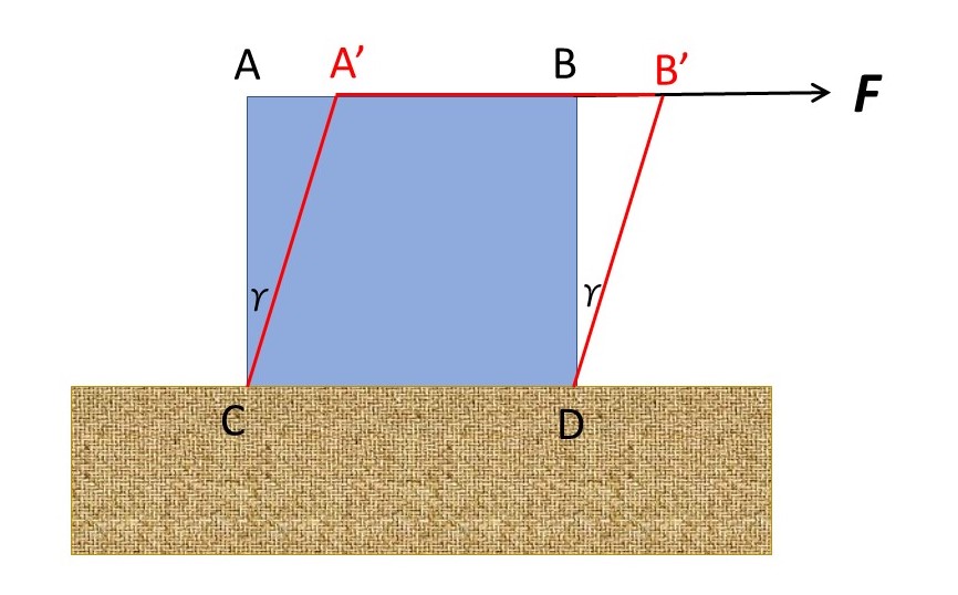
In many books, the subject of shear is introduced by a picture like the one above. Here a cube is fixed to a base (shown in brown) and is deformed by a force, F, acting along its upper surface. This diagram makes it easy to understand why F/A is defined to be shear stress and γ is defined to be shear strain. However, the cube in this picture is not subject to pure shear because A’C > AC and B’D > BD. This deformation is sometimes called simple shear.
Note that true shear is accompanied by tension and compression. In the second figure B’D’ > BD, so that, in the direction of f, the cube has been placed in tension. This result is not surprising because the effect of f is to pull the cube in the direction of BD. Similarly, A’C’ < AC so there is a compressive strain in this direction. We could consider compression in this direction to be a result of Poisson’s ratio (post 20.5) because it is perpendicular to the tensile direction.
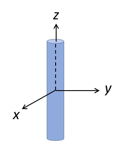
A tensile strain that is not in the direction of a principal axis of strain is always accompanied by a shear strain. To understand the concept of this principal axis, look at the picture above. If a stress is applied in the direction of the axis of the cylinder, the z-axis in the figure, the change in shape (to create a longer, thinner cylinder) can be considered solely as changes of dimension in the x (compressive strain), y (compressive strain) and z (tensile strain) direction. The axis of the cylinder is a principal axis of strain.
Similarly, a tensile stress, that is not applied along a principal axis of stress, will generate a shear stress in an object. We can see, intuitively, that in the picture, the principle stress direction is the same as the principle strain direction because the effect of the stress is to cause changes of strain in the x and y directions that can be considered to be caused solely by stresses in these directions. For objects with less symmetry, the directions of the principal stress and principal strain may not coincide. To explore this subject further, we would need to consider stress and strain as tensors (post 20.2) which requires a knowledge of matrix algebra. (If you are familiar with matrix algebra, think of this as an eigenvector problem).
We can express the stiffness of the material of an object, when it resists shear, by the shear modulus or rigidity modulus defined as
n = σs/γ.
This definition of n is analogous to the definition of Young’s modulus, in post 20.2, and is measured in the same units.
It appears that we could describe any deformation of an object as a combination of tensile, compressive and shear strains. However, it is sometimes convenient to think of deformation in other ways. I hope to give an example in my next post.
Related posts
20.9 Stiffness and strength
20.6 Elasticity
20.5 Poisson’s ratio
20.3 Hooke’s law
20.2 Deformation of objects
Follow-up posts
20.20 Deformation of objects – isometric compression
20 22 Relation between Young’s modulus and shear modulus
21.17 Beams
21.21 Torsion
