In post 20.15, we saw how to calculate the forces that could maintain a system in equilibrium. We developed equations, by equating the vector sum of the forces acting on the system and the vector sum of the torques acting on the system, that could be solved to find the forces. But suppose the equations did not have a unique solution; this means the system could be in equilibrium under more than one set of forces. A system like this is called a statically indeterminate system.
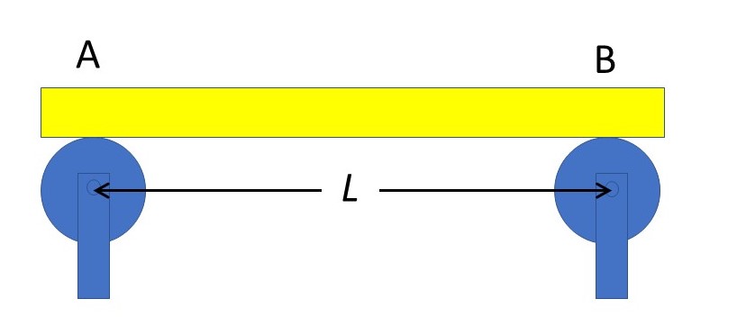
Now let’s think about a horizontal beam resting on two rollers, a fixed distance L apart, at A and B, as shown in the picture above. To keep things simple, we’ll assume that the mass of the beam and the friction between the beam and the rollers is negligible.

Now let’s suppose that a vertical force, F, is applied to the beam, mid-way between the rollers. The beam will bend, as shown above, for the reasons described in post 21.17. The picture in post 21.17 exaggerates the curvature – the deflection in a real beam would be much less. But, in this post, I want to consider a beam that could deflect this much, or more. We don’t know the exact shape of the curved beam, especially because it is loaded at a point. Notice that the beam contacts each roller at a point. This point contacts both the beam and the roller, so it must lie on a common tangent to the curves of both; a tangent is a line that touches a curve at a point. As the beam bends, it pushes against the roller. The reaction force normal to the common tangent (RA at A and RB at B) makes an angle, θA, with the vertical at A and θB at B, as shown. Notice that in post 21.17, we considered beams to be supported by the apices of two triangles, so that θ = 0.
Since the system is symmetric about a vertical line passing through the centre of the beam, the moduli of RA and RB must be equal, so that we can write
RA = RB = R (1)
Similarly θA = – θB,
so that we can write
θA = – θ and θB = θ (2).
Now let’s try to calculate the value of R, in the same way that we calculated the forces that maintain a system in equilibrium in post 21.15. We can use either of the methods (vector or scalar, described in post 21.15) to obtain the results given below. From the horizontal components of the forces acting on the system we obtain
Rsinθ + Rsin(-θ) = Rsinθ – Rsinθ = 0.
This result tells us nothing. The vertical components tell us that
F = 2Rcosθ,
which means that
R = F/(2cosθ) (3).
If we can find another equation that relate R, F and θ, we can solve the two simultaneously to find R. Following the method of post 21.15, we equate the torques acting about one of the rollers to zero, to obtain
F = 2Rcosθ.
Rearranging this result gives us equation 3. Equating torques acting about the other roller, gives us the same result – because of the symmetry of the system.
The result is that we have two unknowns, R and θ, but only one equation relating them to F. So there are many pairs of values of R and θ that can lead to equilibrium – we have a statically indeterminate system.
What do the textbooks tell us to do now? They tell us to make assumptions that enable us to develop more equations, until we can obtain a unique solution.
Let’s see how that works. We’ll assume that the curvature of our beam is negligible. Then θ = 0 and equation 3 becomes
R = F/2 (4).
How can we be sure that this method is reliable? We can’t! If the curvature of the beam is appreciable, equation 4 will be incorrect.
In practice, if we are trying to analyse the forces acting on an existing structure, we can make measurements to see if our assumptions are reasonable. For example, in our example, we could measure θ and, if it were very small our result would be a reliable estimate for R.
If we are designing a structure, we have to be sure that our assumptions are very reliable, if we are going to predict the behaviour of the system we are designing.
The human spine provides an example of a statically indeterminate system where making invalid assumptions may lead to unreliable results. The spine consists of a series of cylindrical, rigid bones (called vertebrae) joined by cylindrical, flexible couplings (called intervertebral discs). When the spine is in equilibrium it is subjected to passive forces (the restoring forces in stretched ligaments) and active forces (the forces exerted by muscles) as described in post 18.9. Over 40 years ago, it was recognised, by Alan Yettram and M Jackman, that the spine is a statically indeterminate structure. But people wanted to calculate the forces acting on it, especially when lifting weights, to investigate possible causes of back pain. They did this by assuming that the spine does not change its curvature during lifting. But, when you read their published work, it appears that most of them didn’t realise that they were investigating a statically indeterminate structure.
Richard Aspden, then at the University of Manchester, showed that, according to this model, lifting normal weights could fracture the vertebrae. We know that vertebrae fracture sometimes and that fractured bones can heal (see posts 20.14 and 20.15). But he believed it was unreasonable that the vertebra were constantly subjected to such high loads. So, he proposed that the spine changes its curvature, during lifting. Then the assumption that was made to deal with a statically indeterminate system would be invalid and the results obtained would be incorrect. Later, at the University of Aberdeen, he and his colleagues used MRI to image the spine during lifting and showed that its curvature did change.
Statically indeterminate systems show that solving physical problems may not be as simple as writing down some equations and solving them.
Related posts
