Before you read this, I suggest you read posts 21.17 and 21.19.
This post is a continuation of post 21.19. I am going to use the ideas in post 21.19 to develop the equations stated, without proof, in post 21.17, that allow us to calculate the deflection and maximum stress in two examples of beams: a cantilever loaded at its free end and an evenly loaded beam supported at both ends.
We will assume that the curvature of the loaded beam is small (the radius of curvature is large). Then we saw in post 21.19 that
σ = εE = Eu(d2y/dx2) (1)
(from equations 1 and 6 in post 21.19) and that
(d2y/dx2) = T/(EI) (2)
(equation 9 in post 21.19).
Here x and y are the Cartesian coordinates of a point in the beam (x is horizontal, in the direction of the beam, and y is vertical, as shown in the pictures below) and u is a distance, in the y direction of a point in the beam from its neutral axis; further details are given in post 21.19. E is the Young’s modulus of the material of the beam, T is the torque, resulting from the restoring force, exerted by a cross-section of the beam and I is the second moment of area of the cross-section of the beam. Again, there are more details in post 21.19.
Now we’re going to apply equations 1 and 2 to our two examples.
1 A cantilever loaded at its free end
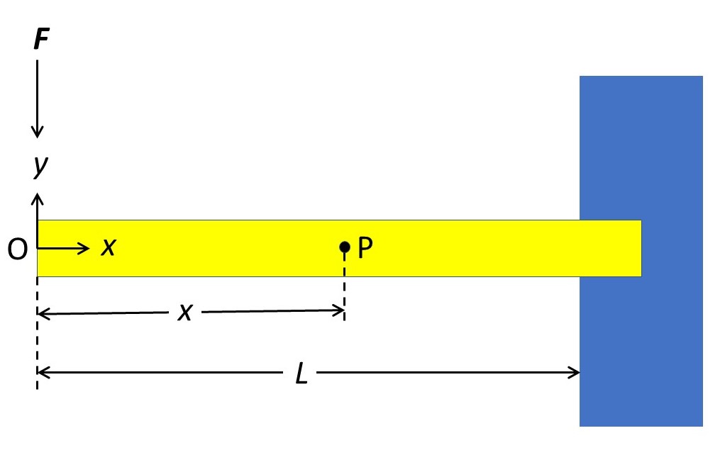
In the picture above, a horizontal cantilever is fixed at the right-hand side. The centre of the cross-section of the free end defines the origin, O, of a Cartesian coordinate system (described above). P is a point at a horizontal distance, x, from O and L is the length of the beam. When a force of modulus F is applied to O, the beam will curve slightly downwards. The torque exerted by this force at P has a modulus Fx; it is positive, by convention, because it acts in an anticlockwise direction. A cross-section of the beam at P is in equilibrium when it exerts an equal and opposite torque of – Fx. Substituting this result into equation 2 gives
EI(d2y/dx2) = -Fx (3).
To solve this differential equation, we integrate both sides with respect to x with the result that
EI(dy/dx) = –(Fx2/2) + C (4)
where C is a constant of integration; to find out more about integration see post 17.19.
We now apply the boundary condition that when x = L, dy/dx = 0, since the cantilever is joined to its support at this point. Then
0 = –(FL2/2) + C C = FL2/2.
Substituting this value for C into equation 4 gives
EI(dy/dx) = (FL2/2) – (Fx2/2).
Integrating again gives
EIy = (FL2x/2) – (Fx3/6) + K (5)
where K is another constant of integration. We now apply the boundary condition that when x = L, y = 0, again the cantilever is joined to its support at this point. Then
0 = (FL3/2) – (FL3/6) + K
so that
K = (FL3/6) – (FL3/2) = -2FL3/6 = –FL3/3.
Substituting this value of K into equation 5 gives
y = F(-x3 + 3L2x -2L3)/(6EI).
We are now going to use this result to find the deflection of the cantilever.
The deflection is given by the maximum vertical distance of a point on the axis of the beam from O. Since the beam is loaded at its free end, this must be given by this distance when x = 0, that is when
y = -2FL3/(6EI) = –FL3/(3EI).
The negative sign arises because the deflection will be in the direction of the negative y-axis. Then the deflection of the beam is given by
y’ = FL3/(3EI)
which is identical to the result stated (without proof) in equation 5 of post 21.17.
From equations 1 and 3, the stress in the beam is given by
σ = Eu(-Fx/I) (6).
This means that the stress is zero at the free end of the beam (x = 0) and is greatest when x has its maximum possible value of L. The tensile stress is also greatest at the top surface of the beam and the compressive stress is greatest at the bottom surface – both at a distance h/2 from the neutral axis, when h is the height of the beam (see the third picture in post 21.19). So the maximum stress in the beam is
σmax = (Eh/2)(FL/I)
which is identical to the result in equation 5 of post 21.17.
If something is worrying you about the signs in this result for the maximum stress, read this paragraph: if not, ignore it. You may be concerned that the top of the beam is defined by u = +h/2 but this gives a negative stress (that is a compressive stress instead of a tensile stress) when substituted into equation 6. The reason is that the equations in post 21.19 were derived for a downward (negative) slope of the curvature; the way I have defined the coordinate system here, the slope is in the opposite direction. Then we need to replace (d2y/dx2) in equation 1 by -(d2y/dx2).
2 A beam evenly loaded along its length
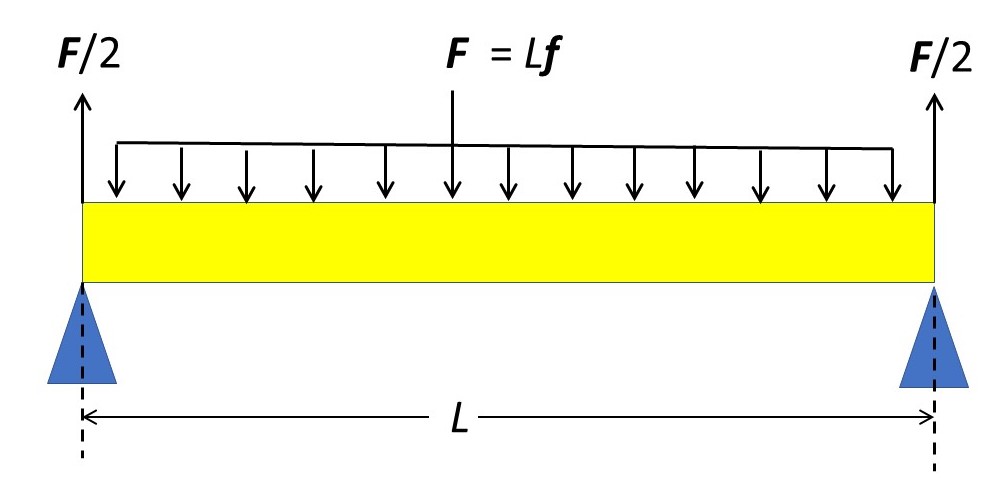
Here, I am thinking about a beam supported at both ends, like the second picture in post 21.17 but now the force F is not applied at the centre but evenly along the length of the beam. The modulus of this force, for a unit length of beam is them f = F/L where L is the length of the beam. For a uniform beam the modulus of reaction force at each support must be identical and equal to F/2. The pattern of loading and, therefore, the geometry of the beam when it bends on the right-hand side must be the mirror image of the left-hand side. The beam is shown in the picture above but I have not tried to represent the curvature of the bent beam because it is very small; this curvature is exaggerated in the third picture of post 21.17.
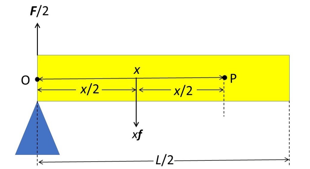
The picture above shows the left-hand side of the beam. I am now going to define the origin, O, of my Cartesian coordinate system at the centre of the cross-section of the beam immediately above the support; the x and y-axes are defined as in example 1. I am going to consider a cross-section of the beam that contains the point P that has coordinates (x, y). The reaction force at the support is equal to F/2 = fL/2; it exerts a clockwise (by convention negative) torque on P of –fLx/2. There is also a force fx that creates a torque on P in the opposite direction. This force acts evenly along the length x of the beam between O and P. It is equivalent to a force fx acting at the centroid of part of the beam between O and P, that is at a distance x/2 from O. The torque exerted by this force is fx2/2. So, the total force exerted on P is fx2/2 – –fLx/2. For the cross-section of the beam that contains P to be in equilibrium, it must exert a torque of
T = – fx2/2 + fLx/2 = f(Lx – x2)/2.
Substituting this result into equation 2 gives
EI(d2y/dx2) = f(Lx – x2)/2 (7).
As in example 1, we integrate equation 7 to get
EI(dy/dx) = fLx2/4 – fx3/6 + C’. (8)
where C’ is a constant of integration. When the beam bends, its curvature must pass through a minimum at the centre – see the third picture is post 21.17 remembering that the beam is symmetric about its centre. So, we can apply the boundary condition that (dy/dx) = 0 when x = L/2 with the result that
0 = (fL/2)(L/2) – (f/6)(L/2)3 + C’.
If you have managed to follow this up to here, you will be able to do a bit of algebra to show that
C’ = fL3/24.
Substituting this result into equation 8 gives
EI(dy/dx) = fLx/2 – fx3/6 – fL3/24.
Integrating again gives
EIy = fLx2/4 – fx4/24 – fL3x/24 + K’ (9)
where K’ is a constant of integration. When x = 0, y = 0 so that
0 = 0 + 0 + 0 +K’ so that K’ = 0.
Substituting this result into equation 9
EIy = (fx/24)(2Lx2 – x3 – L3).
When we found a value for C’, above, we saw that the maximum deflection of the beam (the point where its curvature passes through a minimum) occurs when x = L/2. Substituting this value for x into the equation above gives a maximum deflection of
y’ = (fL/48)(1/EI)(L3/2 – L3/8 – L3) = (fL/348)(5L3)(1/EI) =(5FL3)/(384EI).
This result is stated, without proof, in equation 4 of post 21.17.
From equations 1 and 7, the stress in the beam is given by
σ = [(Eu)/(EI)](fLx/2 – fx2/2) = [(fu)/(2I)](Lx – x2)
The maximum stress in the beam is given where the strain is maximum, that is where the deflection is maximum (x = L/2) and when u = h/2, for the reason given in example 1. Substituting these vales into the equation above gives
σmax = [(fh)/(4I)][L(L/2) – (L/2)2) = (fhL2)/(16I) = (FLh)/(16I).
This result is stated, without proof, in equation 4 of post 21.17.
This post and post 21.19 show that a lot of thought is needed to understand something as apparently very simple as the deflection and stress in a beam.
Related posts
