Before you read this, I suggest that you read posts 22.1, 22.2 and 22.3.
The picture shows a microscope. Light passes through a bi-convex lens called the condenser and then through a thin specimen that scatters the light. This scattered light then passes through another lens called the objective. The objective acts in the same way as the lens of a projector, to produce a real image. But, in the microscope, this image is not formed on a screen. Instead, the light continues through the eyepiece. The eyepiece is a magnifying glass that produces a virtual image from the real image. The microscope in the picture gives a choice of three objectives. In the picture, the shorter of the three has been rotated in position to view the specimen. The source of the light is at the focal point of the condenser, so parallel rays of light pass through the specimen.
This type of microscope is called a transmission light microscope – “transmission” because the light passes through (another way of saying “transmitted by”) the specimen. And “light” because light is used to form the image.
The source of light is at the focus of the condenser so that the rays of light that meet the specimen are parallel (see post 22.1).
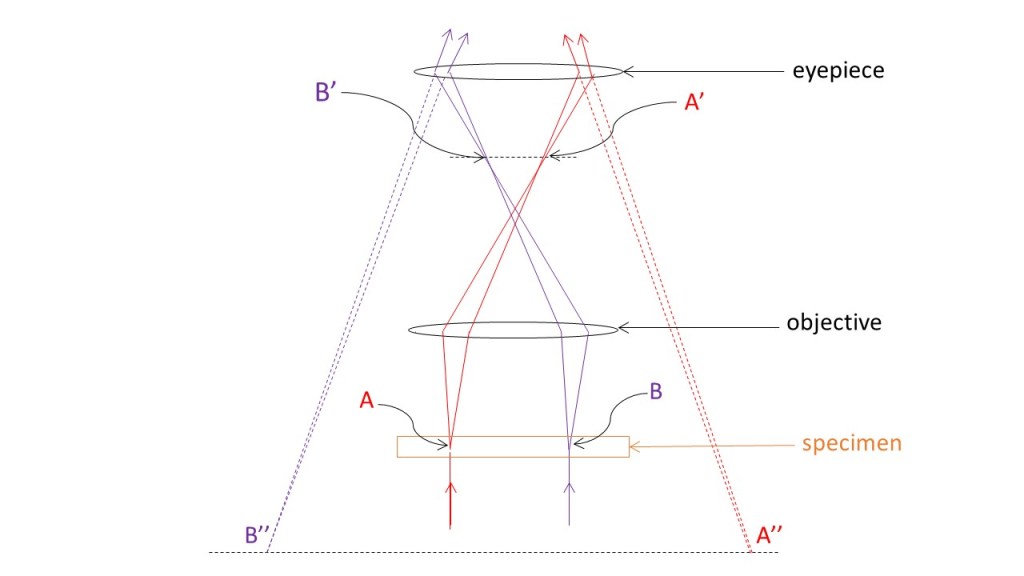
The picture above uses ray tracing to show that the image is magnified at each stage. I have showed the path of the rays that pass through A, in the image, in red and the path of rays that pass through B in purple. The objective forms a magnified, real inverted image, A’B’, that is further magnified by the eyepiece to produce a virtual image, A’’B’’, like the magnifying glass in post 22.3. The overall magnification of the microscope is the magnification of the two lenses multiplied together; more details are given in the appendix. In this picture the condenser, objective and eyepiece have the same principal axis – called the optical axis of the microscope. But, in the microscope shown in the first picture, the optical axis is bent by a prism – to make it easier to look into the eyepiece.
This picture is a section through the microscope. In three dimensions, the specimen is very thin and so is almost a plane – perpendicular to the optical axis. The real image then also lies in a plane, that contains points A’ and B’, perpendicular to the optical axis.
In the picture above, the real image is viewed by a camera so that it can be converted into a image that can be stored by a computer and viewed on a screen. Then the objective forms a real image – exactly as before. But the camera lens forms a second real image, like the projector in post 22.2. The total magnification of the image is the magnification of the objective multiplied by the magnification of the camera; more details are given in the appendix.
Not all microscopes use light – they can use other types of electromagnetic wave or particle waves (see wave-particle duality), for example electrons. Some microscopes use reflected waves. And others don’t use the systems of lenses shown in the picture above. Instead, they use a something like the camera lens, in the picture above, to examine many positions in the specimen and form a magnified image of each. For example, a conventional scanning electron microscope (SEM) scans a specimen surface to produce an image from the reflected electrons. A camera detects light from a fluorescent screen that emits light when electrons hit it. In a conventional transmission electron microscope (TEM), electrons pass through the very thin specimen and magnets are used to bend the paths of the electrons to form an image, in the same way as in a conventional light microscope. You can work out what a scanning transmission electrons microscope (STEM) does for yourself!
Related posts
22.1 Refraction at curved surfaces
22.2 The projector
22.3 The magnifying glass
Follow-up posts
22.13 Resolution of the microscope
22.12 Diffraction…
Appendix
Magnification of the image in the microscope
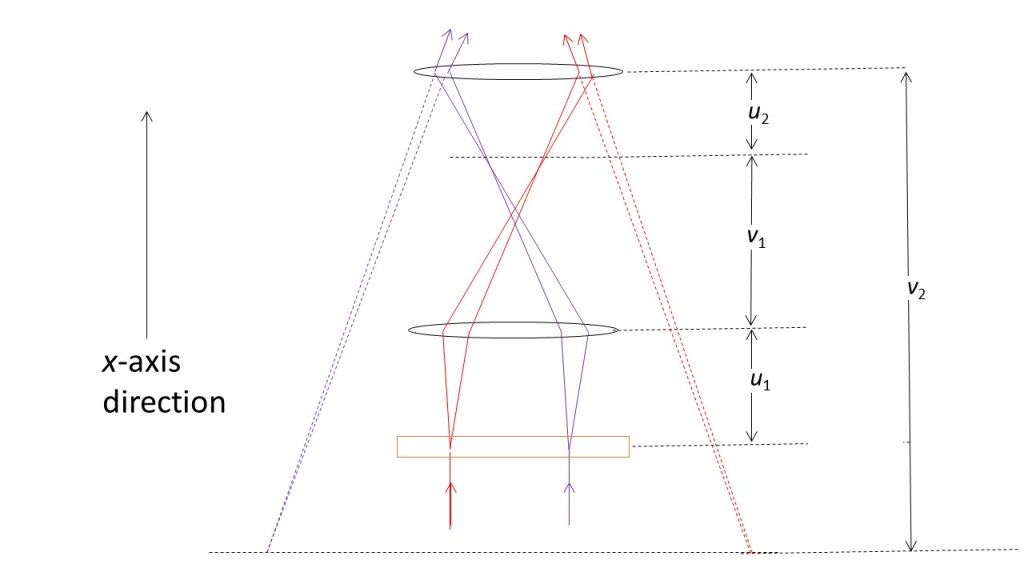
For a given objective, the distance between the objective and eyepiece is fixed. In the picture above this distance is v1 + u2. These two lenses are fixed at opposite ends of a tube. This tube can be moved in the x-axis direction until the user sees a clear image of A and B through the eyepiece (at A” and B”). Since most people are comfortable seeing an image at a distance of 25 cm (see post 22.2), the microscope is designed to have v2 = 25 cm.
In general, the distance of an object, u, and an image, v, along the principal axis of a lens, of focal length f, are related by
1/f = 1/v – 1/u
(see post 22.1). Applying this to the eyepiece gives
1/f2 = 1/(–25) – 1/u2
where all distances are now measured in cm, and v2 is negative because it is in the negative x-axis direction (using the Cartesian sign convention), relative to the centre of the eyepiece. Here f2 is the focal length of the eyepiece. Therefore
u2 = -25f2/(f2 + 25).
The negative sign arises because u2 is in the negative x-axis direction. And the magnification (see post 22.3) is given by
m2 = v2/u2 = 25/u2 = -(f2 + 25)/f2.
This magnification is negative because the image is virtual. All this is consistent with the eyepiece acting as a magnifying glass.
Now, considering the objective, with focal length f1, we have
1/f1 = 1/v1 – 1/(-u1) = 1/v1 + 1/u1
since u1 is in the negative x-axis direction, relative to the centre of the objective. Then
v1u1 = f1(v1 + u1).
Since the objective is a projector (see post 22.2) its magnification is
m1 = v1/u1 = f1(1+ v1/u1).
The total magnification of the microscope is given by multiplying m1 and m2.
If we replace the eyepiece with a camera lens to project a real image on to a detector at a distance v2 from the lens (in the positive x-axis direction)
m2 = v2/u2.
