Before you red this, I suggest you read post 22.1.
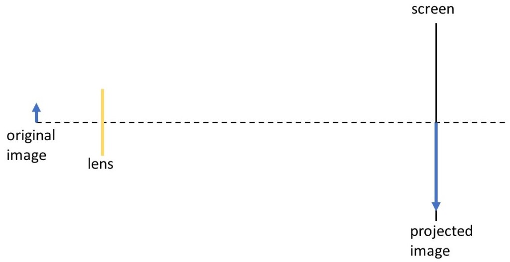
A projector is a device that uses light emitted by an original image to produce a larger version of that image on a screen (the projected image), as shown in the picture above. In this picture the blue arrow points upwards but in the projected image it points downwards; we say that the image is inverted. If we want the object to point upwards, we simply need to invert the original image.

In this post, we shall see how a projector uses a bi-convex lens to produce the projected image. In early projectors the original image appeared on a semi-transparent film; light, from a bright source behind the film, was used to form the projected image (left-hand side of the picture above). Movies used a rapidly changing sequence of such images to produce a moving projected image on the screen (right-hand side of picture above). In a data projector, the original image is formed from a computer output.

The picture above shows why the projected image is inverted, using the technique of ray-tracing. Rays are shown in red. The original image is perpendicular to the principal axis of the lens. A ray, from the top of the object, parallel to this axis is bent by the lens so that it passes through its focal point; a ray from the same point that passes through the centre of the lens is not bent – all this is explained in post 22.1. The two rays joint to recreate this point in the projected image but we can see that it is now below the principal axis – so the image has been inverted.
If we traced rays from an object in a plane perpendicular to the pictures above, we would see that points on the right-hand side of the original image appeared on the left of the projected image and points on the left-hand side would appear on the right. But this isn’t a problem because we simply need to orient the original image so that we see the projected image we want.
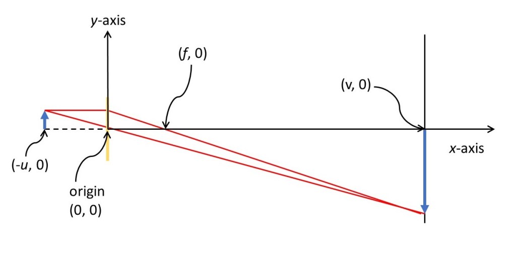
Using the conventions of post 22.1, we make the centre of the lens the origin of a Cartesian coordinate system; the x-coordinate of the original image is –u and the x-coordinate of the original image is v, as shown in the picture above. The coordinates of some important points are shown (in brackets) on the picture. According to post 22.1, u and v are related by
1/f = 1/v – 1/u (1)
where f is the focal length of the lens. The value of f is determined by the refractive index of the glass of the lens and the curvature of its surfaces – so has a fixed value that is positive for a bi-convex lens – all this is explained in post 22.1.
To obtain a sharp image on the screen, the positions of our original images, lens and screen must satisfy equation 1. Usually the position of the original image is fixed and we place the screen where we want to see the projected image. The lens is then moved, in the principal axis directed to satisfy equation 1 and produce a sharp (focussed) image. (Often the lens is mounted in a device that can be screwed in or out of the body of the projector, in order to move it along the principal axis).

If equation 1 is satisfied for the top of the object is must also be satisfied for any other point in the original image, as shown in the picture above. So every point in the original position appears in a focussed projected image.
In the appendix, I show that the magnification of the image is given by
m = v/u. (2)
When we use equation 2, we will assign a negative value to u (because it is in the negative x-axis direction) and a positive value to v. The numerical value of m will then be negative – showing that the image is inverted, because it points in the negative y-axis direction.
The type of image that we see on the screen is called a real image. This means that the image is really there – we could draw round the outlines of the objects and colour them to make a copy of the projected image.
How long will the technology I have described here last? Already most people used an LCD screen to view their photographs at home. Larger versions are becoming more common for outdoor displays because they work in daylight. Perhaps one day they (or some similar technology) will be used for cinema screens and optical projectors will be a relic of the past.
Related posts
22.1 Refraction at curved surfaces – lenses
Follow-up posts
22.3 The magnifying glass
22.11 The microscope
Appendix
The purpose of this appendix is to derive equation 2.

In the picture above h is the height of the original image and h’ is the height of the projected image.
Since the ray that passes through the centre of the lens (the red line) is not bent, it must make a constant angle with the principal axis (the horizontal black line). On the left-hand side of the lens, the tangent of this angle is given by
tanθ = h/(-u).
The minus sign shows that u is in the minus x-axis direction. On the right-hand side of the lens, the angle is given by
tanθ = – h’/v.
Here the minus sign shows that v is in the minus y-axis direction.
From these two results
h’/h = v/u.
But h’/h is the magnification, m, so that m = v/u.
