In post 25.10, I defined the magnetic field, B, caused by an electric current, I1, in a long straight wire, at a point given by a vector r, perpendicular to the wire, by
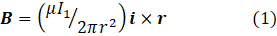
where μ is the permeability of the stuff surrounding the wire, and i × r is the cross product of a unit vector, i, in the direction of the current and r.
You may have been taught this definition and the other stuff in this post without using vector algebra. But then you had to learn Fleming’s rules and when to apply them. Understanding electromagnetism then becomes a complicated memory test with strange empirical rules. It’s much simpler to learn some simple vector algebra by reading posts 17.2 (two-dimensional vectors), 17.3 (three-dimensional vectors), 17.13 (appendix 2, dot product) and 17.37 (cross product).
In post 16.25, I stated the empirical result that currents I1 and I in parallel straight wires exerted a force per unit length on each other whose modulus is
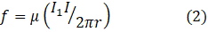
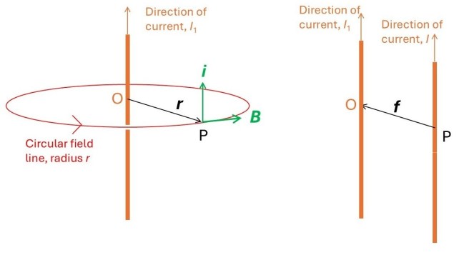
where r is now the distance between the wire. I hope the pictures above make the descriptions relating to equations 1 and 2 easier to understand.
Then the modulus of the force between currents in two parallel straight wires of length L is
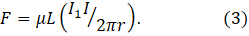
When I1 and I are in the same direction, this force causes the wires to attract each other.
From equations 1 and 3, the modulus of the force on a current in a long, straight wire of length L is then

Equation 4 doesn’t tell us anything about the direction of the force. If we want to know this direction, we need the vector equation that I am going to derive next.
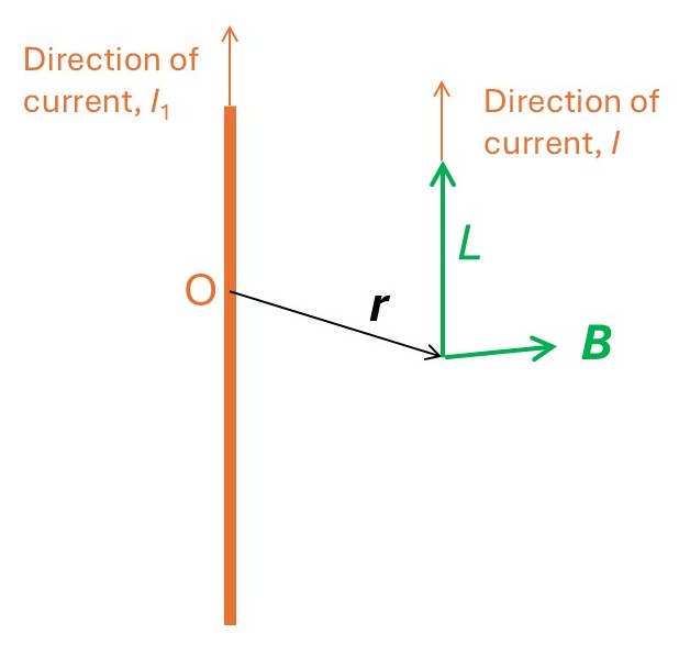
The picture above shows a point P on a straight wire, conducting a current I1, that is parallel to a straight wire conducting a current I. The magnetic field, B, at P is a tangent to a circle of radius r, where r is the perpendicular distance between the wires and is perpendicular to the wire conducting the current I (see post 25.16). Since the two wires are parallel, B is perpendicular to the direction of the current I1.
Now I’m going to define a vector L that points along this direction, in the direction in a wire of length L. Since the force between the wires attracts them to each other, its direction is given by L × B., as shown in the picture above. Then equation 4 becomes

which gives a complete description of the force that the magnetic field exerts on the wire.
For a current that doesn’t change with time, in a constant magnetic field, we can write equation 5 as

where v is the velocity of the moving charge that is the current. If we add to this result, the force on a charge in an electric and a magnetic field (see post 17.24), we get an expression for the total force on a charge of

Equation 6 is the form in which the Lorentz law (that we met briefly in post 25.10) is usually given.
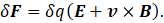
Now I want to think about the force on an infinitesimal charge δq. According to equation 6, this force is given by
Diving both sides of this result by the volume, δV, occupied by this charge gives
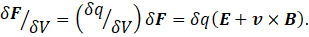
or

where f is the force per unit volume of charge and ρ is the charge density (measured in coulombs per square metre, C.m-3). Defining the current density, J, as ρv, gives

So the total force on a charge in a magnetic field is given by the integral
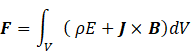
where integration is over the total volume containing the charge. I have dropped the subscript total, because it should now be clear that I am referring to the total force in an electric and magnetic field.
This integral gives a complete description of the force on charge and, therefore, current, in an electric and a magnetic field. We can consider it as a general statement of the Lorentz law.
Related posts
25.16 Biot-Savart law
25.10 Magnetic fields
16.25 Electrical charge
