
A wave bounces back from a wall that it cannot destroy or be propagated through. This bouncing back is called reflection and is shown in the picture above.
We are usually interested in reflection of electromagnetic radiation. For example, light is reflected by a mirror. A mirror is something that cannot absorb or propagate light waves.
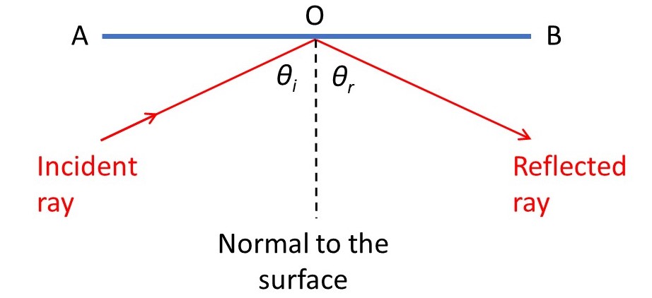
We usually explain reflection, for example the image we see in a mirror, by ray-tracing. In the picture above, the line AB, is where a plane mirror, perpendicular to the plane of the picture, meets the plane of the picture. The incident ray meets AB at O. The line that meets the mirror at O and is perpendicular to it is called the normal to the surface of the mirror. We can explain what we see in the mirror using two simple scientific laws – the laws of reflection. Here is the first:
The incident ray, the reflected ray and the normal to the surface all lie in the same plane.
Now we define the angle of incidence, θi, as the angle between the incident ray and the normal. The angle of reflection, θr, is defined as the angle between the reflected ray and the normal. Our second law of reflection is:
The angle of incidence is equal to the angle of reflection.
These two laws are justified in appendix 1. Do NOT use a laser pointer to investigate the laws of reflection experimentally – it is dangerous and could lead to permanent eye damage. For a safe alternative see https://www.youtube.com/watch?v=axKQt0ARypY .
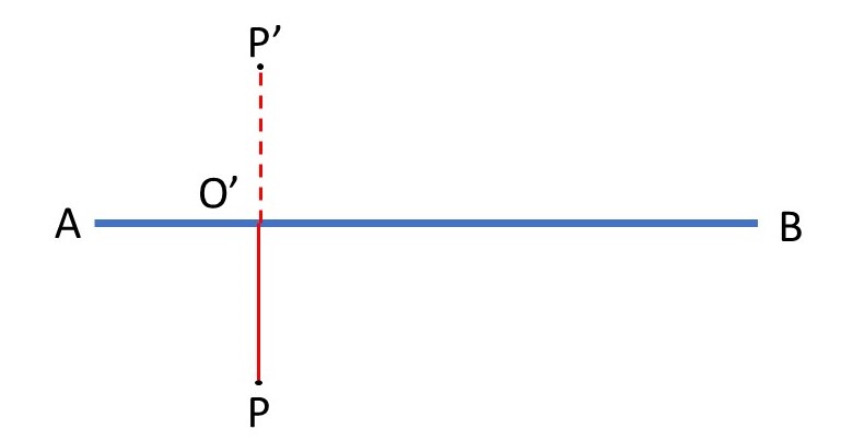
Two important results follow from the laws of reflection. In the picture above P is a point in an object in front of the mirror. P’ is the apparent position of P in the mirror image. Note that P’ doesn’t really exist – if you look behind the mirror you won’t see an image there! P’ is where the point corresponding to P appears in the reflection of the object. The mirror tricks our eyes into seeing something that isn’t there. This is explained in appendix 2. The two important results are that
PP’ is perpendicular to AB
and
PO’ = O’P’
where O’ is the point where PP’ intersects AB. Appendix 2 shows how these results can be derived from the laws of reflection. These results mean that, when a point is reflected in a mirror, there is a point in the image that is directly in front of it (behind the mirror) and that the original point and the reflected point are the same distance from the reflecting surface.
Now hold something in your right hand and look at yourself in a mirror. Your image appears to be holding the thing in its left hand. But its head is at the top of its body – just like yours! These results are explained in the last sentence of the previous paragraph. Everything in the reflected image appears to be directly in front of the corresponding thing in the real object. So the thing you are holding is on your right-hand side which is in the left hand of your image – because your image is pointing in the opposite direction to you. Remember that right and left are defined relative to a person, so that when someone faces you, his/her right is your left. The head of the image is directly above its body because it is directly opposite your head.
In the past, some people used to carry a small mirror with them – to check their appearance. But it’s not necessary now because you can use the camera on your phone.
Related posts
20.27 Chirality
19.21 Refraction
Follow-up posts
22.5 Total internal reflection
22.6 Reflection at concave surfaces
23.02 Bragg’s law
Appendix 1
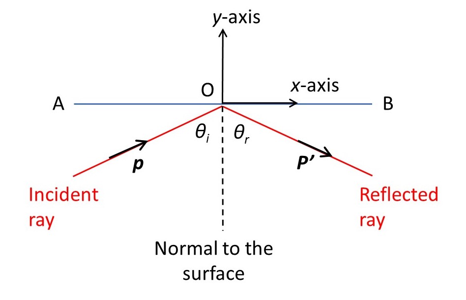
The purpose of this appendix is to derive the laws of reflection. In the picture above, the incident ray meets the mirror, AB, at O, the origin of a Cartesian coordinate system. The x-axis lies on the surface of the mirror, in the same plane as the incident ray and the normal to the surface at O; the y-axis forms a right-handed coordinate system.
Usually we consider a ray to be the direction of propagation of a wave; we can then use the properties of waves to derive the laws of reflection. In post 19.21 I used this approach to derive the laws of refraction. But if we are thinking of electromagnetic radiation, like light, we could equally well consider a ray as the direction in which photons are travelling. We define p to be the momentum of incident photons with an angle of incidence θi; note that p is a vector. If i, j and k are unit vectors in the direction of the x, y and z-axes (the z-axis is perpendicular to the plane of the picture and points towards you) then
p = i(psinθi) + j(pcosθi) + k0.
where p is the modulus of p. Since a photon has no mass, you may wonder why its momentum is not zero; this is explained in appendix 3. Collision with a smooth wall in the x-axis direction cannot change the k-component of the momentum, so the momentum of the reflected photons is
p’ = i(p’sinθr) + j(p’cosθr) + k0
where p’ is the modulus of p’. These two equations show that p and p’ are in the same plane as i and j which are defined to be in the same plane as the normal to the surface; this is the first law of reflection.
Now let’s suppose that the photon does not lose energy in its collision with the mirror – it is an elastic collision. Then p and p’ must be equal (see appendix 3). Collision with a smooth wall in the x-axis direction cannot change the i-component of the momentum so that
psinθi = p’sinθr.
Since p = p’ this becomes
psinθi = psinθr.
If p is not equal to zero, we can divide both sides of this equation by p to give
sinθi = sinθr or θi = θr
which is the second law of reflection.
Appendix 2
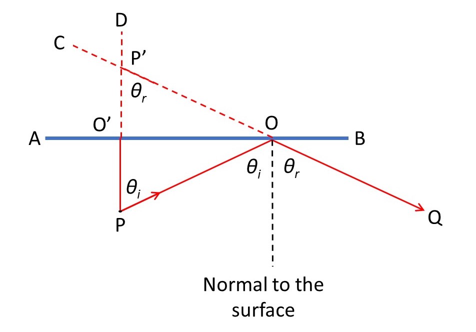
The purpose of this post is to show that PP’ is perpendicular to AB and that PO’ = O’P’. In the picture above, P is a point in an object in front of the mirror AB. A ray from P that is perpendicular to AB meets the mirror at O’. PD is the extension of PO’. PO is a ray from P that has an angle of incidence of θi and an angle of reflection of θr; it is reflected along the path OQ. QC is the extension of QO.
Then rays O’P and OQ appear to come from the intersection of PD and QC which is the point P’. Since PP’ is parallel to the normal to the surface, the angle OP’O’ must be equal to θr; if it weren’t PP’ would intersect the normal at some point and the lines would not be parallel. Similarly, OPO’ must be equal to θi, for the same reason.
Since PP’ is perpendicular to AB, the angles P’O’O and PO’O are both 90o. And, since the sum of the internal angles of a triangle is 180o, angle O’OP’ equals 90 – θr degrees and angle O’OP equals 90 – θi degrees.
Now let’s look at the triangles OO’P’ and OO’P. From the properties of the tangent of an angle
tan(90 – θr) = O’P’/O’O and tan(90 – θi) = O’P/O’O.
Since θr = θi (laws of reflection), O’P’/O’O = O’P/O’O or O’P’ = O’P.
Appendix 3
This post is concerned with the modulus of the momentum of a photon.
A photon must have the same speed, c, in a vacuum as an electromagnetic wave. The modulus of its momentum is then defined to be
p = mc so that m = p/c.
One solution to these equations is that p = m = 0. Now remember that a wave transmits energy not matter (see post 18.10). So, if we think of the mass of our photon being annihilated it gives energy
E = mc2
according to Einstein’s theory of relativity (see post 17.41). Then
E = (p/c)c2 = p/c
so that
p = Ec.
If the energy of the photon and, therefore, the energy of the wave, is non-zero then p is non-zero.
